A comprehensive guide on Gear Pump
Define the gear pump.
The gear pump is a PD (Positive displacement) pump. It helps to develop a flow by carrying the fluid between repeatedly enclosing interlocking gears or cogs, transferring it automatically using a cyclical pumping action. So, the hydraulic gear pumps provide a smooth pulseless fluid flow whose rate depends on its gears’ rotational speed.
How does the gear pump work?
The gear pump uses rotating gears or cogs action to move fluids. Its rotating part forms a fluid seal by the casing of the pump and creates suction at the inlet of the gear pump. Fluid pulled into a gear pump is surrounded by the rotating gears or cogs cavities and shifted out to discharge.
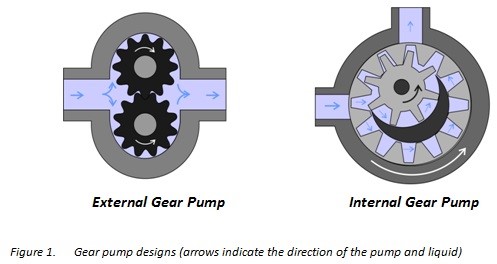
Types of Gear Pump
The gear pump is classified into two major types:
➣ External Design Gear Pump
➣ Internal Design Gear Pump (Figure 1).
1. External Design Gear Pump
External design Gear pump contains two identical and interlocking gears that are supported through separate shafts. The motor is used to drive the first gear which drives the second gear. In a few cases, electrical motors can drive both shafts that are supported with bearings on every side of the casing.
- When gears move out from the mesh on the pump’s inlet side, they form an extended volume, Fluid flows into the pump’s cavities and is entrapped by the edges of the gear while gears carry on rotating against the casing of the pump.
- The entrapped fluid comes out from the Pump’s inlet towards the discharge side around the region of the casing.
- When gear’ edges get interlocked on the Pump’s discharge side, the volume decreases and fluid forces out underneath pressure.
The fluid cannot be transferred back over the center, amongst the gears, as they got connected. Close tolerances amongst the casing and the gears let the external gear pump extend suction over the inlet and prohibit fluid from going back from the pump’s discharge side (Though the low viscosity fluids have more tendency for fluid leakage).
The external designs gear pumps can utilize herringbone, helical, or spur gears.
2. Internal Design Gear Pump
The Internal Design Gear Pump works the same as of External Design Gear Pump except that it’s both interconnected gears have different sizes where one rotates inside of the others. It has a larger internal gear which is called the rotor i.e. its edges projecting from the inside. The other external gear of small size is mounted into the center of the rotor which is called the idler.
It is designed for interconnecting with the outer rotor in a way that the edges of the gear engage at one end. The bushing along with a pinion is attached to the casing of the pump which holds the inner idle into its location. A crescent shape fixed divider fills the vacant place which is created by the idler’s irregular mounting position. It works like the seal amongst outlet & inlet ports.
- When gears move out from the mesh on the pump’s inlet side, they form an extended volume, fluid flows into the pump’s cavities, and is entrapped by the edges of the gear while gears carry on rotating against the partition and casing of the pump.
- The entrapped fluid comes out from the Pump’s inlet towards the discharge side around the region of the casing.
- When gear’ edges get interlocked on the Pump’s discharge side, the volume decreases and fluid forces out underneath pressure.
The internal design gear pump can only use the spur gears.
Describe the basic features and advantages of the gear pump.
The gear pump has a few moving parts and is very simple and compact. Its pressure power cannot be matched with reciprocating pumps or the rates of flow of the centrifugal pumps. Yet it provides higher throughputs and pressures than lobe pumps or vanes. The gear pump is specifically suitable for fluids of high viscosity and pumping oils.
From the two types of gear pumps, the external design has the ability to sustain high flow rates and pressures (more than 3000psi) due to its closer tolerances and stronger shaft support. Internal design provides better suction. It is suitable for fluids of high viscosity but it provides an operating range of 1cp to more than 1,000,000cp. As output depends on the rotational speed, the gear pump is mostly used for blending and metering operations. The gear pump can also be engineered for handling aggressive liquids. Whereas it is generally made from stainless steel or cast iron, new composites and alloys let the pump handle corrosive fluids like sodium hypochlorite, sulphuric acid, sodium hydroxide, and ferric chloride.
The external design can be used in lifting machinery, hydraulic power, plant equipment, and vehicles. When the gear pump is driven in reverse, by using the oil which can be pumped from anywhere in the system (generally through a tandem pump within an engine), creates the hydraulic motor. It can be beneficial for providing power in those fields where the electrical system is costly, inconvenient, or bulky. For example, a tractor depends on an external design engine-driven gear pump to power its services.
Describe the limitations of the gear pump.
The gear pump is self-priming yet it can also dry lift, though its priming features can be enhanced by wetting the gears. The gears should not run dry for a prolonged period and must be lubricated through a pumped fluid. Some designs of gear pumps can be operated in both directions (forward or reverse). Since the same gear pump can be utilized for loading and unloading the vessel, for instance.
Close tolerance amongst the casing and gear means that this pump type is vulnerable to wear especially when feeds consisting of entrained solids or abrasive fluids are used. Though, few pump designs, specifically internal variants let to handle the solids as well. The external design gear pump has four bearings with tight tolerances. Therefore, it is less suitable to handle abrasive fluids. The internal design gear pump is more robust and has just one bearing (maybe two) to run in a fluid. The gear pump needs to install a strainer on a suction side that can protect it from potential damage to solids.
In general, when a gear pump requires for handling abrasive solids then it’s better to choose a pump with a higher capacity that can be run at low speed to avoid wear. But it must keep in mind that the gear pump’s volumetric efficiency becomes lessens at low flow rates and speeds. The gear pump must not be run beyond the recommended speed.
In applications of high temperature, it’s necessary to make sure that an operating range of temperature is compatible with the specification of the pump. Gears and casings’ thermal expansion lessens clearances in the pump which can lead to increased wear as well as in extreme circumstances, pump failure.
In spite of the best precautions, the bearings, casing, and gears of the pump succumb to wearing with every passing day. As there is an increase in clearances, a gradual decrease in efficiency happens along with an increase in the flow slip: pumped fluid’ leakage from the expulsion back towards a suction side. The flow slip depends on the clearance’ cube between the casing and cog edge so, practically, wear provides a small impact till a critical stage is reached after which the performance of the pump degrades rapidly.
Gear pumps continue to pump in contrary to reverse pressure then if downstream blockage happens, it will carry on to the pressurized system till the pipework, pump, or other parts fails. Due to this reason, some gear pumps are used to equip the relief valves. It’s advisable to use a relief valve anywhere within a system for protecting the downstream equipment.
The internal design gear pumps that operated at less speed are considered ideal for shear-sensitive fluids like paint, soaps, and foodstuffs. The lower clearances and higher speeds of eternal design gears make them appropriate for these kinds of applications. The internal design gear pump also prefers where hygiene conditions are more important due to its mechanical simplicity. This is a fact that it has easy-to-clean, strip-down, and reassemble features.
Describe gear pumps’ main applications.
Gear pumps are appropriate for pumping fluids of high viscosity like foodstuff, oil, paints, or resins. They are used in any kind of application where the output of high pressure or accurate dosing is required. The gear pump output is not affected too much by pressure and they can be used in any type of situation where irregular supply occurs.
The applications of external design and internal design gear pump are enlisted in the table below:
| Gear Pump designs | External design | Internal Design |
| Various lube oils and fuel oils |  |
|
| Polymer metering and chemical addictive | |
|
| Chemical blending and mixing | |
|
| Mobile hydraulic, agriculture, and industrial applications | |
|
| Caustic and acids(composite or stainless steel construction) | |
|
| Polymers and resins | |
|
| Solvents and alcohols | |
|
| Tar, bitumen and asphalts | |
|
| Pigments, inks, and paints | |
|
| Polyurethane foam (polyol and isocyanate) | |
|
| Food products: animal feed, corn syrup, cocoa butter, sugar, vegetable fats, peanut butter, chocolate, fillers, vegetable oils | |
|
| Surfactants and soaps | |
Summary
The hydraulic gear pumps help to develop a flow by carrying the fluid between repeatedly enclosing interlocking gears or cogs, transferring it automatically to a smooth pulseless flow of which rate depends on its gears’ rotational speed. Two basic design types of gear pumps are external design and internal design.
External design Gear pump contains two identical and interlocking gears that are supported through separate shafts. The Internal Design Gear Pump has two interconnected gears having different sizes where one rotates inside of the others.
Gear pumps are appropriate for pumping fluids of high viscosity like foodstuff, oil, paints, or resins. They are used in any kind of application where the output of high pressure or accurate dosing is required. The external design gear pump is used to sustain high pressure (more than 7500 psi) while the internal design gear pump provides better suction and is more suitable for fluids that are shear sensitive and of high viscosity!